Introduction
|
| |
A lot more has been said than written about the legendary Pringle's
Can Wi-Fi antenna, and a lot more people have talked glowingly about
them without ever actually using one. Look closely, and you'll
see that you have to add various things to it to make it work even
so-so. Unless you have a can with a foil lining (not all Pringle's
cans that I've seen do) and unless you can make good electrical
contact to that foil lining (not a slam-dunk, trust me!) the can
won't act as a waveguide antenna and thus won't throw your signal
very far or bring in anything from a distance.
Don't obsess on the Pringle's solution. There's an easier kitchen-trash
antenna to be had: The Tetra Brik Soup Box. Even as recently as
mid-2002 these were uncommon in the United States, though they have
been around for years in Europe. Now, however, Swanson's Chicken
Broth in a Tetra Brik can be found in almost any major supermarket.
In most health food supermarkets you can also find non-dairy milk
substitutes (rice milk, soy milk, oat milk, etc.) in 32-oz Tetra
Brik containers.
In this brief Web-based how-to I won't go into gruesome detail
on the physics of waveguide antennas. I spend a lot of time on that
in my book, and if you're curious about how it all works, please
pick up a copy. Be aware, however, that you're building a rectangular
waveguide antenna. The calculations are somewhat different than
for circular waveguide antennas, like coffee can, spaghetti can,
or (yes) Pringle's can antennas.
|
What You'll Need and
What You're In For
|
| |
The process of making a Tetra Brik antenna involves some knife
work, a little—very little!—soldering, and (horrors!)
some calculator math. Use a sharp knife or single-edged razor
blade. A dull knife will mostly just deform the cardboard and put
you in danger of getting yourself sliced up. Whatever you use, be
careful.
The necessary materials are these:
- A Tetra Brik of a suitable size. More on this below.
- About 2 inches of #12 or #14 copper wire. This is just a scrap,
and it's the gauge of wire commonly used in house wiring. If there's
a construction site nearby, look in the dirt or in the site dumpster
for scraps.
- A silver-plated type N male coaxial connector, chassis (that
is, 4-hole) mount. More on this below.
- Four round-head machine screws, size 4-40, 1/2" long.
- Four 4-40 next nuts for the above screws.
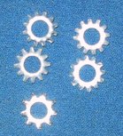
- Eight "spiny" lockwashers (see photo at right) of
a suitable size for the above screws. These, by the way, are very
important! I'll explain why later on.
- (Optional) A handle or bracket of some kind. What this turns
out to be depends on how you intend to use the antenna. More on
this below.
You'll need these tools:
- A sharp knife or single-edged razor blade. A round needle file
with a sharp point ground on its tip is also useful for making
screw holes in the cardboard Brik.
- A small soldering iron, and a scrap of electrical solder. (Don't
use acid-core metalworking solder!) You don't need much.
- A small screwdriver and nut driver for the size of the hex nuts
that you use. The nuts are usually 1/4" in diameter.
- If you intend to make a metal bracket or handle, you'll need
a drill of some kind, to drill holes for the N connector and four
mounting screws. The handle is optional; some people (in keeping
with the kitchen-trash nature of the project) just use duct tape.
If you're still up for it, let's get to work.
|
Step 1. Get Yourself
a Brik!
|
| |
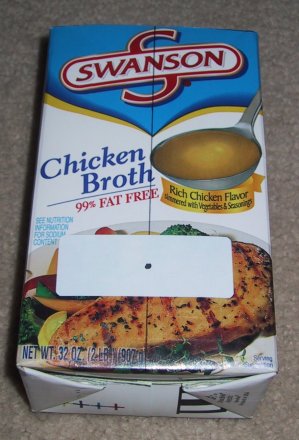
Above are three common products packaged in Tetra Brik containers.
All of the Briks that I've seen in stores are of a suitable size
for Wi-Fi antennas, but that may not always be the case in the future,
so be prepared to do some measuring. The Swanson 1 quart (32 oz)
soup boxes are the ones I've had most experience with. They are
65 X 95 X 165 millimeters. The Tetra Brik container (as opposed
to the soup) is a European product, hence the metric measurements.
Since I first wrote this tutorial, I've begun seeing one-quart Briks
that are a little bit smaller in cross-section but a little bit
taller, and measure in at 58 X 90 X 195 mm. I think this new size
is an Americanization of the package, as its English measurements
are 2 1/4" X 3 1/2" X 7 5/8". This is not different
enough to cause a problem; however, anything more than about 50%
larger than the Briks shown here may not be suitable at the 2.4
GHz Wi-Fi frequencies.
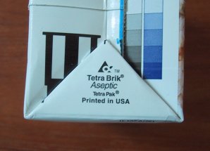 At
right I show the logo at the bottom of the carton. Look for it. At
right I show the logo at the bottom of the carton. Look for it.
Make the soup for lunch (I recommend adding some Egg-n-Onion Matzo!)
and you're there.
The outside surface of Tetra Brik containers is slick and waxy-feeling,
and doesn't take pen or pencil markings very well. Use a fine-point
permanent marker like a Sharpie to put lines on the Brik for cutting
or hole-poking.
|
Step 2. Cut the End
Off and Clean It Up
|
| |
Take a sharp knife or single-edged razor blade and cut off
the top of the Tetra Brik as cleanly as you can. Tip: cut about
an eighth of an inch down from the top of the box. For the cleanest
cut, draw good straight lines in Sharpie marker on the brik where
you intend to cut, and follow the lines with the knife or razor
blade.
Discard the cut-off end (you won't need it, except perhaps for
practice in poking or drilling screw holes) and clean the inside
of the Brik well with soap and water. Most soup has garlic and/or
onion powder in it, and the last thing you want is an antenna that
smells like bad Italian cooking. Besides, the worse it smells, the
more likely it is that your dog will haul it off into a corner and
shred it for you.
|
Step 3. Measure the
Brik and Calculate the Feed Point Dimension
|
| |
I've seen (and used) two suitable sizes of Tetra Brik container
in American supermarkets, and I suspect that as they become more
popular in the US, even more sizes will become available. The
size of the Brik is critical to calculating the correct feed point.
What works for one size will work less well (or perhaps not at all)
for a different size. You must measure the Brik and calculate a
feed point dimension for that particular Brik.
There are basically three calculations that must be done: 1) The
free space wavelength for the frequency of the Wi-Fi channel
that we're using; 2) the cutoff wavelength for the Tetra
Brik that we've chosen; and 3) the guide wavelength for the
Tetra Brik that we've chosen. The guide wavelength calculation depends
on the first two calculations, so they must be done in order as
explained below. Note that the calculations are best done using
metric units, because the speed of light is very close to 300,000,000
meters per second.
The free space wavelength depends only on the microwave
frequency at which Wi-Fi operates. For Wi-Fi channel 6, the frequency
is 2.437 GHz, which is the same as 2437 MHz. Free-space wavelength
can easily be calculated by dividing the speed of light in millions
of meters per second by the frequency, in millions of cycles (Hertz)
per second. Because both values are numbers of millions, the "millions"
cancels out, and you can use a formula like this to calculate the
free-space wavelength in meters:
300
-----
2437
This yields .1231 meters, or 12.31 centimeters. That's your free
space wavelength. Channel 6 is the center of the Wi-Fi band in the
US. If you calculate your antenna for Channel 6 it should actually
work fairly well all across the band. On the other hand, if you
want to calculate a value for one of the two ends of the band, use
the frequencies of 2412 MHz for Channel 1, or 2462 MHz for Channel
11.
The second calculation is even easier: The cutoff wavelength is
twice the width of the Brik's long face. (Not the Brik's
length!) For the Swanson's Brik, that's 95 mm X 2, or 190 mm, which
is 19 cm. "Cutoff wavelength" is just that: The wavelength
beyond which the antenna will not work effectively. This isn't an
issue for Wi-Fi, which has a wavelength of 12.5 cm at its longest.
The value, however, must be plugged into the next calculation.
The final calculation is for the Brik's guide wavelength value.
This is a little more involved, and is a function of the frequency
and the geometry of the waveguide. The formula doesn't render well
using any graphics tools I have, so I'll express it in Pascal:
GuideWavelenth = 1 / SQRT(SQR(1/FreeSpaceWavelength)-SQR(1/CutoffWavelength));
Express all values in meters, not centimeters or millimeters.
In other words, rather than use 12.31 centimeters for free space
wavelength, type it into your calculator as .1231 meters. Ditto
cutoff wavelength. The result value will also be in meters.
Here's an example for practice. Plug the values into the equation
to see if you come out with the same answer!
- Channel 6 free space wavelength = .1231 m.
- Cutoff wavelength for 95 mm wide Brik = 2 X .095 m = .190 m
- Guide wavelength (from formula above) = .1616 m.
With the calculated guide wavelength figure in hand, divide it
by four to yield the feed point offset from the bottom of the Brik:
- Feed point offset = .1616 / 4 = .040 m.
That's the crucial value for the next step.
|
Step 4. Mark the Feed
Point and Make the Hole
|
| |
 The
feed point is positioned along a line down the center of the front
face of the Brik. There is a seam down the center of the back face
which will make mounting the N connector difficult. That's why you
must use the front face. Unless you're paranoid about the final
appearance of the antenna (and hey, it's made out of kitchen trash,
right?) I recommend drawing a line down the length of the front
face, at the center, as shown in the photo. The
feed point is positioned along a line down the center of the front
face of the Brik. There is a seam down the center of the back face
which will make mounting the N connector difficult. That's why you
must use the front face. Unless you're paranoid about the final
appearance of the antenna (and hey, it's made out of kitchen trash,
right?) I recommend drawing a line down the length of the front
face, at the center, as shown in the photo.
Measure your feed point offset value from the bottom of the Brik
along the center line of the front face. In the photo at left, I
stuck a white self-adhesive address label to the Brik so that the
mark indicating the feed point would not be lost amidst the details
of that vegetable medley, heh.
Next, draw a circle centered on the feed point spot, 5/8"
in diameter. This is the diameter of the coaxial N connector flange
that must pass through the wall of the Brik. Using a very sharp
knife or razor blade, carefully cut out the 5/8" circle completely
and discard the round piece.
At this point, set the Brik aside. We need to make the probe assembly.
|
Step 5. Make the Probe
Assembly
|
| |
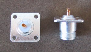 The
probe consists of a male N coaxial connector with a short length
of #12 or #14 copper wire soldered into its "solder pot."
At left is a photo of a pair of silver-plated N connectors, which
I purchased from Fleeman, Anderson,
& Bird. Nickel-plated N connectors can be had for less,
but they may not be "microwave-friendly" due to lossy
insulation material. Go for silver. Be suspicious of anything with
yellow or non-white insulation around the solder pot. Some older
and cheaper N connectors use phenolic insulation, which is lossy
at microwave frequencies. The
probe consists of a male N coaxial connector with a short length
of #12 or #14 copper wire soldered into its "solder pot."
At left is a photo of a pair of silver-plated N connectors, which
I purchased from Fleeman, Anderson,
& Bird. Nickel-plated N connectors can be had for less,
but they may not be "microwave-friendly" due to lossy
insulation material. Go for silver. Be suspicious of anything with
yellow or non-white insulation around the solder pot. Some older
and cheaper N connectors use phenolic insulation, which is lossy
at microwave frequencies.
Find a piece of #12 copper wire about 2" long.
#14 will do, but it's thinner and bends more easily. #12 is a common
size in residential electrical wiring, and you can find scraps lying
around almost any construction site. Remove any insulation. Straighten
the piece of wire as completely as you can. Solder the wire into
the N connector's solder pot, which is the little copper-colored
protrusion pointing upward in the right hand photo above.Make sure
that the wire is perpendicular to the connector's flange. If it
solders crooked, re-melt the solder and straighten it.
The touchiest measurement in the whole Tetra Brik antenna project
is the length of the wire in the probe assembly. The length is the
free-space wavelength divided by four. For Channel 6, that would
be 123.1 millimeters divided by 4, or 30.77 mm. Now, the idea here
is to do your best. Admittedly, measuring a fraction of a millimeter
is a dicey business, and although the closer you come, the more
sensitive your antenna will be on Channel 6.
When you're talking accuracy to the millimeter, the question of
where to measure from is significant. One end, obviously,
is the tip of the wire probe. If you cut it unevenly, file it with
a small file so that it's reasonably rounded and flat on the end.
The other end of the measurement is to the level of the white Teflon
insulation that surrounds the solder pot of the N connector. That's
key: You're measuring from the probe tip to the point where the
solder pot emerges from the coaxial structure of the connector.
It's best to measure it a millimeter or so on the long side, and
then carefully file the tip to bring it down to the final desired
length. But once you've got it to the correct length, the probe
assembly is done.
|
Step 6. Mount the Probe
to the Brik
|
| |
 Place
the probe point-down on the Brik, with the point passing through
the 5/8" hole you cut in the front face of the Brik. Center
the N connector body on the line you drew on the Brik. Take a marker
and mark the four mounting holes onto the Brik, as shown at left.
Placing a mailing label on the Brik (as I show here) helps to make
the marked points more visible. Place
the probe point-down on the Brik, with the point passing through
the 5/8" hole you cut in the front face of the Brik. Center
the N connector body on the line you drew on the Brik. Take a marker
and mark the four mounting holes onto the Brik, as shown at left.
Placing a mailing label on the Brik (as I show here) helps to make
the marked points more visible.
The holes you need to poke through the Brik for the four mounting
screws are small, about 7/64". An awl will work, and some jackknives
have something trekkers call a drill, which is really a type of
awl. I use a round needle file with a sharp point ground on the
tip. If it's sharp it will do the job. Using a needle file allows
you to make a crisp, clean hole by poking the file through the cardboard
and then filing the holes to a diameter that will pass the mounting
screws.
You can also use a hand drill or Dremel tool with a 7/64"
bit. Drilling cardboard is trickier than it sounds; experiment on
the discarded top of the Brik if you're not experienced in drilling
flimsy materials. Tip: Insert a length of 2" X 2" pine
lumber into the Brik so that you're drilling through the cardboard
into the wood, The wood will support the Brik and make for cleaner
holes.
After drilling or poking the four mounting holes, take a razor
blade and trim away any cardboard protruding from the holes into
the Brik. You want the holes to be as smooth as possible so that
the screw heads will lay flat against the plastic/foil liner, and
not against cardboard gouged out of the outer layers.
This next step is probably the trickiest part of the project, aside
from measuring the probe length. The trick lies in the way the Brik
is made, and how the N connector body must have good, four-point
electrical contact to the Brik's inner foil layer. The Brik is a
three-layer construct: A cardboard box contains a thin foil inner
lining, which in turn is coated with a thin plastic film to keep
the Brik's contents from attacking the foil liner. The four screws
that mount the probe assembly to the Brik must contact the
foil. This is not easy!
 The
way I found works best is to use eight spiny lock washers. As shown
in the technical drawing at right, the lock washers go under the
heads of the four mounting screws, as well as under the hex nuts
on the other side of the N connector's square flange. When you tighten
down the hex nuts, use a nut driver and push them hard. You must
tighten the hex nuts sufficiently hard so that they force the lock
washer spines through the thin plastic film covering the foil, allowing
the washers to make electrical contact with the foil. For the
Brik antenna to work well, the Brik's foil liner must contact the
N connector body! The
way I found works best is to use eight spiny lock washers. As shown
in the technical drawing at right, the lock washers go under the
heads of the four mounting screws, as well as under the hex nuts
on the other side of the N connector's square flange. When you tighten
down the hex nuts, use a nut driver and push them hard. You must
tighten the hex nuts sufficiently hard so that they force the lock
washer spines through the thin plastic film covering the foil, allowing
the washers to make electrical contact with the foil. For the
Brik antenna to work well, the Brik's foil liner must contact the
N connector body!
Test it with an ohmmeter after tightening the four hex nuts: Touch
the N connector body with one probe, and force the tip of the other
probe through the plastic film layer to contact the foil liner.
If you don't get solid continuity, you're not done. Tighten the
hex nuts a little more and test for continuity again. If necessary,
carefully abrade away the plastic film over the four mounting
holes with the finest sandpaper you can find. Don't sand too hard
or you'll destroy the foil underneath, which means you'll have to
have some more soup for lunch and start from scratch with a new
Brik! (Note: Make sure your test probes are
sharp enough at their tips to pierce the plastic film layer to the
foil
beneath. If necessary, file or bench-grind at least one one needle-sharp.)
|
Step 7. Attach the Brik
to a Handle Or a Bracket
|
| |
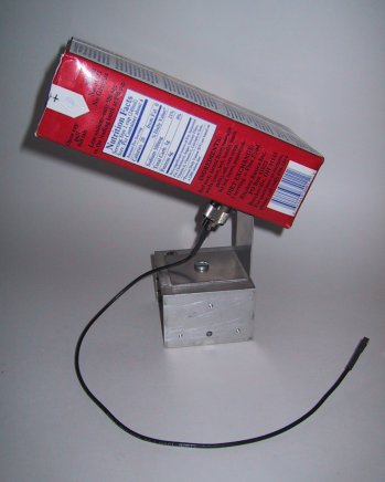 An
antenna like this needs to be mounted to be useful. What sort of
thing you mount it to depends on how you intend to use it. It can
be used as a "bandwidth expander" to bring a Wi-Fi marginal
connection up to full bit rate. I detail how this situation occurred
to me in my book in Chapter 15. I was getting only 1 Mbps (if I
could connect at all) from my living room coffee table, because
my metal-filled kitchen lay on a long path between the coffee table
and my wireless access point. Using a simple soup-box antenna on
a home-made stand, I was able to point the antenna toward the access
point and immediately bring the connection up to full speed. Precision
aiming was not required. An
antenna like this needs to be mounted to be useful. What sort of
thing you mount it to depends on how you intend to use it. It can
be used as a "bandwidth expander" to bring a Wi-Fi marginal
connection up to full bit rate. I detail how this situation occurred
to me in my book in Chapter 15. I was getting only 1 Mbps (if I
could connect at all) from my living room coffee table, because
my metal-filled kitchen lay on a long path between the coffee table
and my wireless access point. Using a simple soup-box antenna on
a home-made stand, I was able to point the antenna toward the access
point and immediately bring the connection up to full speed. Precision
aiming was not required.
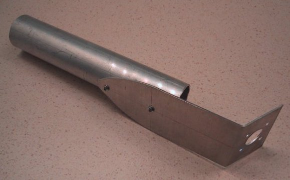
The bracket is nothing more than a scrap of aluminum bent in a
vise and drilled for the 5/8" body of the N connector and the
four 1/8" mounting holes. The bracket in turn is bolted to
a scrap aluminum heat sink, which provides nothing more than ballast
to keep it upright.
Another obvious support would be a camera tripod. The hole in the
bottom of the bracket shown in the photo at left has a 1/4"
diameter hole, to match the 1/4-20 thread stud standard on most
inexpensive tripods.
The antenna can also be used for warscanning—that is, for
standing in one place, perhaps on a hill ot atop a tall building—and
manually scanning the vicinity for accesspoints using NetStumbler.
I've used a photo tripod as a support for warscanning on occasion,
but I also created a sort of "pistol grip" handle for
Wi-Fi antennas so that I can aim them by hand. The pistol grip antenna
is more portable without a tripod, though it's a little trickier
to aim steadily enough to allow your stumbling utility to pick out
the really faint ones. The pistol grip is shown in the photo below:
As a matter of habit, I only mount my home-brew Wi-Fi antennas
by the N connector. This allows me to use any bracket or handle
for any antenna, and I can mix'n'match as needed. (I haven't yet
made an antenna so massive or heavy that it can't be mounted by
its N connector...but that day will come.) This also allows you
to make as few holes in the Brik as possible, which is good. The
more screw heads and holes in the Brik, the more signal scattering
will occur inside the Brik, and the higher your noise level will
be.
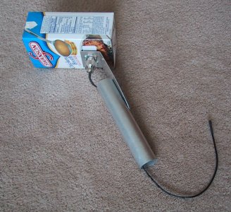 At
left is the same handle mounted to the Brik antenna I've just described.
Using a handle with a Wi-Fi waveguide antenna (like this one) takes
a steady hand and some patience. The longer the waveguide, the fussier
the aiming of the antenna is, and this is about as long a waveguide
antenna as you can usefully aim by hand. At
left is the same handle mounted to the Brik antenna I've just described.
Using a handle with a Wi-Fi waveguide antenna (like this one) takes
a steady hand and some patience. The longer the waveguide, the fussier
the aiming of the antenna is, and this is about as long a waveguide
antenna as you can usefully aim by hand.
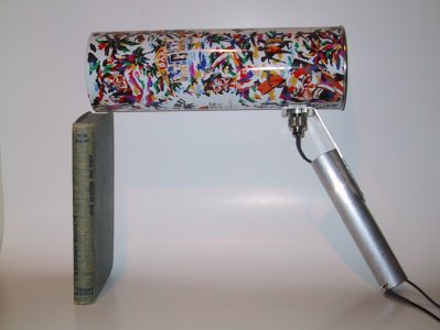
As an example of a waveguide antenna that's a little
too long, see the picture at lower right. The can is steel, and
contained a bottle of Malibu spiced rum. I was able to use it effectively
when it was mounted to a camera tripod, but trying to warscan by
holding it in my hand failed completely.
 I
cover the use of tin cans and the calculations that go with them
at great detail in my book. The rum can antenna would work better
if it were shortened by three or four inches. Any waveguide antenna,
furthermore, works better with a flared metal horn at the "mouth,"
but that's a lot of fussy metalwork and I won't go into the calculations
in this simple how-to. For more about horns used with Brik antennas,
see this
site. A full-fledged general-use Javascript horn designer can
be found here.
If you're good with a tinsnips and a (heavy-duty) soldering iron,
you can make an excellent waveguide antenna horn with copper roof
flashing. I
cover the use of tin cans and the calculations that go with them
at great detail in my book. The rum can antenna would work better
if it were shortened by three or four inches. Any waveguide antenna,
furthermore, works better with a flared metal horn at the "mouth,"
but that's a lot of fussy metalwork and I won't go into the calculations
in this simple how-to. For more about horns used with Brik antennas,
see this
site. A full-fledged general-use Javascript horn designer can
be found here.
If you're good with a tinsnips and a (heavy-duty) soldering iron,
you can make an excellent waveguide antenna horn with copper roof
flashing.
|
Done! Now, how good
an antenna is it?
|
| |
My testing shows that it's way better than a Pringle's can, but
not quite as good as a Hunt's Spaghetti Sauce can. (I explain in
considerable detail how to build the Hunt's cantenna in Chapter
15 of my book.) Much depends on how good an electrical connection
you can manage between the Brik's foil lining and the body of the
N connector. If the antenna doesn't appear to perform for you, that's
the first thing you should check. Use an ohmmeter with two probes
with good sharp points, and test electrical continuity between the
body of the N connector and the foil lining of the Brik. If you
don't get a kick to zero ohms, tighten the screws with the spiny
lockwashers. Keep in mind that it's the lockwasher spines that pierce
the insulating transparent plastic film and allow connection to
the inner layer of aluminum foil. Without that connection, you don't
have a waveguide antenna, and your results will be down in the trash
somewhere.
Also check that you measured the probe wire correctly and that
it's as close as possible to the calculated length. At microwave
frequencies, an eighth of an inch counts.
|
Software, Sources, and
References
|
| |
Wardriving Software:
- NetStumbler.com,
for the NetStumbler and MiniStumbler utilities.
- Aerosol,
a simple wardriving utility for Windows that supports some
USB client adapters, including Linksys WUSB11. Good device
support, fairly minimal feature set. Requires a protocol driver
like WinPCap.
- Kismet is probably
the most commonly used wardriving utility for Linux. It works
in monitor mode and can detect APs whether or not their broadcast
beacons are operating.
- AirTraf,
a curses-based (i.e., text mode) wardriving utility for Linux.
A CD-bootable version for Windows users is promised; this
will boot into Linux without affecting the underlying system.
Not available yet.
- DStumbler
is part of BSD-Airtools, and is a curses-based wardriving
utility for BSD Unix.
- MacStumbler is
similarly the leading utility for the Mac. OS/X only, and
so far requires AirPort wireless hardware.
- KisMac is a wardriving utility
for Mac OS/X that works in monitor mode (like Kismet, its
only relationship thereto) and can detect APs that have their
beacons disabled.
- PocketWarrior
for PocketPC supports Prism-based clients cards on the PocketPC
platform. Theoretically works with any NDIS 5.1-compatible
Prism driver, but it's always best to check the list of supported
cards.
- WarLinux,
a CD-bootable version of Linux created specifically for wireless
auditing. I haven't used it yet but it's a promising idea:
Configure Linux with all the machinery already in place for
wireless network auditing.
- Warglue
is a suite of console (text-mode) utilities for converting
among the three major wardriving logfile formats: NS1, (NetStumbler)
Kismet, and Wiscan. Warglue also contains a utility for knocking
out defective GPS coordinates from a logfile.
Several other pertinent utilities exist (see the
list at wardriving.com)
but the ones listed above are the main ones.
Pigtails & N Connectors:
- My personal favorite source for wardriving hardware (antennas
and connectors, primarily) is Fleeman,
Anderson, and Bird. They sell goods related to Wi-Fi generally,
but have paid special attention to the sorts of things wardrivers
use. Their omnidirectional mag-mount antenna beats anything
I myself have ever tried, including Pringle's and various
tin-can antennas. They also sell every conceivable type of
pigtail, silver-plated coaxial connectors, and microwave-capable
coaxial cable.
Books on Antenna Theory:
- The
ARRL UHF/Microwave Experimenter's Manual, The American
Radio Relay League, 5th printing, 2000. A steal for $20. This
is where I learned most of my microwave antenna theory, and
is the place to go if you want more details on how these things
actually work.
Other Tetra Brik Tinkerers on the Web:
|
Postscript: Version
of 6/29/2006
|
| |
All material © 2003, 2006 by Jeff Duntemann. All Rights Reserved.
Linking encouraged!
Some (but only a little) of the material in this how-to is adapted
from the latest edition of my book, Jeff
Duntemann's Wi-Fi Guide.
ISBN 1-932111-88-3 $34.99. If you found this how-to useful, please
consider buying the book. It covers Wi-Fi antenna theory and construction
in detail, along with pigtails, coax losses, link budgets, and a
lot of other need-to-know material for extending the range of stock
Wi-Fi gear.
|
|
|
|